
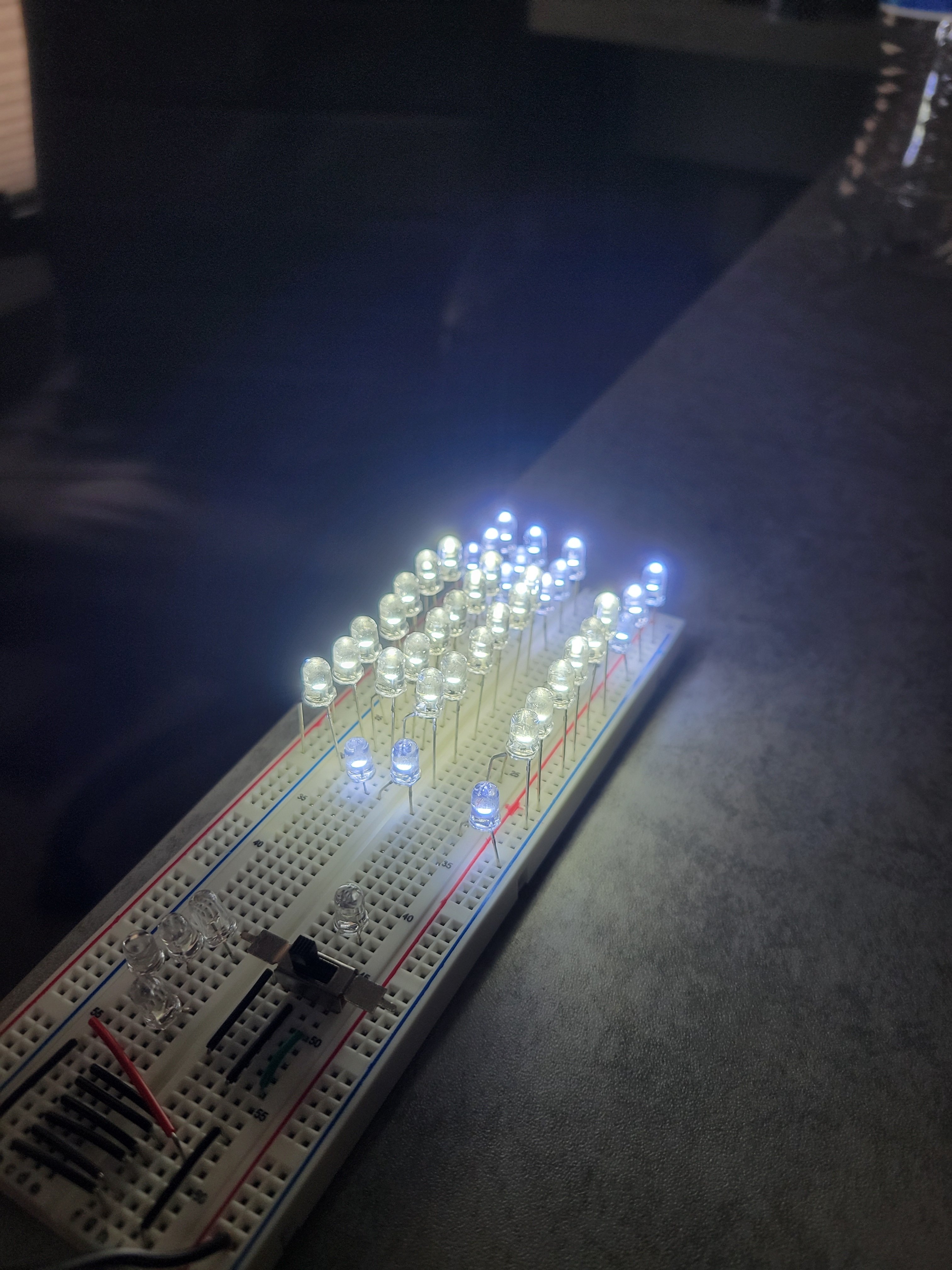
I’ve got the appropriate amount of light for my microscope ring light, but now I need to put it all in an enclosure of some sort.
If I don’t have a custom board to solder these to, what are my best options for connecting these she mounting them into something?
If this is too vague, please let me know if I can clarify
I’m no expert, but I think you might need resistors on those LEDs or they’ll burn out fairly quickly. I cannot see the whole circuit, and my EE classes were a long-ass time ago. It looks like you might be driving them straight from the breadboard’s power. Just wanted to give you a heads up in case it’s an issue.
https://electronics.stackexchange.com/questions/28393/why-do-we-need-resistors-in-led
Good luck!
I had that same thought, but I’m running 4, 3.3V diodes per parallel branch/arm/whatever, with a 12V power supply, so the calculations I’ve seen for determining the appropriate resistor tell me this doesn’t need any.
It felt wrong, but I wanted to see if it would light up, and it did! I tried to wrap this concern into the “is it going to start on fire?” Bit lol
Not only you always need at least a resistor, but matching the power supply voltage to the leds drop will ensure you’ll have a hard time maintaining their brightness on the real world.
If you want to keep it simple, leave 1V or 2V as a margin and add a resistor to get the desired current. If you want to make it fancy, get a led driver.
That being said, I redid it with your input in mind. It’s currently got 100U resistors and draws a good bit more than the power supply is capable of
When you say “the real world” what do you mean, exactly? Because the 12V, 200mA power supply I used to power it for these pictures is likely what will ultimately power it
You have a current limiting power supply. So the power supply transistor is acting as the resistor for you in this scenario.
For example, as the leds on the original circuit age, you can expect a few of those lines to stop getting any current, and the others to get brighter and brighter until they fail.
That can happen very quickly too, if their temperature varies a lot (how much is a lot depends on the leds). Or if you change your power supply for one capable of more current, it’s likely that everything will just fail immediately. Or, if you have a noisy one, you may severely reduce the leds lifetime.
As a rule, you can’t use diodes internal resistance as a power limiter. It does not behave the same way as resistors and will surprise you on every bad way possible.
Huh, if I had the time I’d do some reading about it. Sounds like there’s some really interesting physics going on there